Five DFM mistakes hardware startups make before their first production run
Your prototype works. Your production unit won't. Here are the five manufacturing mistakes that cost hardware startups six figures and six months, and what to do before you commit to tooling.
Five DFM Mistakes Hardware Startups Make Before Their First Production Run
Your prototype works. It looks great on the bench. Investors are impressed. The 3D print feels solid in your hand. You're ready to go to tooling.
You're also about to make mistakes that will cost you six figures and six months, not because you're bad at engineering, but because nobody told you what changes there are between a prototype and a production part.
I've spent five years as a mechanical engineer at a contract product development company, taking products from concept art through mass production. Every project taught me the same lesson: the gap between "works as a prototype" and "manufacturable at scale" is where startups lose the most money. Here are the five mistakes I see most often, and what to do instead.
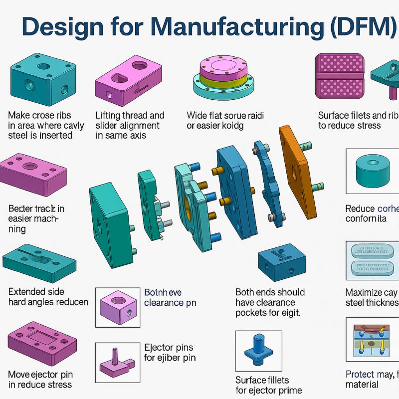
Designing wall thicknesses that won't fill
The mistake: You designed your enclosure with wall thicknesses that vary dramatically, 1.2mm here, 4mm there, because you were thinking about structural strength, not plastic flow.
Why it kills you: Injection molding works by pushing molten plastic through a mold cavity. The plastic flows through the thinnest sections first and struggles to fill thick sections uniformly. When wall thickness varies by more than 25-30% across a part, you get sink marks on thick sections (visible depressions on the cosmetic surface where the plastic shrinks as it cools), short shots where thin sections don't fill completely, and warping as different sections cool and shrink at different rates.
What your 3D print didn't tell you: Additive manufacturing doesn't care about wall thickness variation. A 3D printer deposits material layer by layer and handles thickness changes without complaint. So your prototype looked perfect, and your first injection-molded samples will look terrible.
What to do instead: Aim for uniform wall thickness across the entire part. For most consumer enclosures, 1.8-2.5mm is the sweet spot, thick enough for structural integrity, thin enough for reliable mold filling, and reasonable cycle times. Where thickness variation is unavoidable, use gradual transitions (at least 3:1 length-to-thickness-change ratio) rather than abrupt steps. If you need structural reinforcement in specific areas, add ribs rather than increasing wall thickness. Ribs add stiffness without creating sink marks when sized correctly (rib thickness should be 50-70% of the adjoining wall thickness).
Forgetting draft angles
The mistake: Your CAD model has perfectly vertical walls because that's what the industrial design calls for. Nobody mentioned that the part has to come out of the mold.
Why it kills you: An injection mold consists of two halves that clamp together, are filled with plastic, and then separate to release the part. If your part has vertical walls and zero draft, the part grips the mold core like a suction cup. In each cycle, the ejection system must overcome friction and vacuum forces to push the part out. The result: scuffed surfaces from the part dragging along the mold walls, ejector pin marks where the pins push too hard against the plastic to force it out, and eventual mold damage as the steel wears from repeated high-force ejection.
What your 3D print didn't tell you: A 3D printer builds parts in open air. There's no mold to pull the part out of. So draft angles are invisible to the prototype, and invisible to most startup founders until the mold maker sends back a DFM review covered in red marks.
What to do instead: Add a minimum of 1° of draft to every surface that's parallel to the mold pull direction. For textured surfaces, add more, generally an additional 1° per 0.025mm of texture depth, because texture creates mechanical grip between the part and the mold. Start designing with draft angles from the beginning, not as an afterthought. Most CAD tools have draft analysis features that color-code surfaces by draft angle. Run this check before sending anything to a mold maker.
Ignoring tolerance stackups in multi-part assemblies
The mistake: Each individual part in your assembly has reasonable tolerances. But you never analyzed what happens when all those tolerances stack up across the full assembly.
Why it kills you: A single injection-molded part might hold ±0.1mm on a given dimension. That's fine for one part. But if your product is an assembly of five parts that all reference each other, the cumulative tolerance across the assembly is not ±0.1mm; it's ±0.5mm in the worst case. That half-millimeter gap (or interference) is the difference between parts that snap together cleanly and parts that either rattle or won't assemble at all.
What your 3D print didn't tell you: When you 3D-print an assembly, you often print all the parts on the same machine, from the same material, with the same calibration, sometimes in the same build. The parts fit because they were born together. Production parts come from different molds, run on different machines, are made from different batches of material, across different days. Every source of variation stacks.
What to do instead: Run a tolerance stackup analysis before you commit to tooling. Identify the critical interfaces, snap fits, alignment features, and sealing surfaces, and calculate the worst-case cumulative tolerance for each. If the stackup exceeds your functional requirement, you have three options: tighten individual tolerances (more expensive tooling and slower cycle times), reduce the number of parts in the stackup (simplify the assembly), or add compliance features (flexing snap arms, alignment ribs, gaskets) that absorb variation.
Specifying materials by name instead of by requirement
The mistake: Your BOM says "ABS" because that's what everyone uses. You never asked whether ABS actually meets the functional requirements of your product.
Why it kills you: "ABS" isn't a material; it's a family of hundreds of grades, each with different properties. The ABS you prototype with is not the ABS your manufacturer will quote. Production-grade ABS varies widely in impact strength, heat deflection temperature, UV resistance, flame retardancy, color stability, and mold flow characteristics. Specifying "ABS" on your BOM is like specifying "metal" for a structural beam; it tells the manufacturer nothing about what you actually need, and they'll default to whatever is cheapest and most available.
What your 3D print didn't tell you: Your prototype was probably printed in PLA or a generic photopolymer. It didn't experience sustained UV exposure, repeated impact, thermal cycling, or chemical contact. So you never learned that your enclosure needs UV-stabilized ASA instead of ABS, or that your snap fits need a grade with high elongation at break, or that your battery compartment walls need flame-retardant, V-0-rated material.
What to do instead: Specify materials by performance requirements, not by name. Create a requirements table for each part: operating temperature range, UV exposure (yes/no), impact resistance, chemical exposure, flame rating, cosmetic requirements (color matching, surface finish), and expected service life. Then select a specific material grade that meets all requirements, not just a generic family name. Ask your manufacturer for material data sheets and compare the actual properties against your requirements. If you're not sure which grade to choose, that's exactly the kind of question a DFM review answers before it costs you a production run of unusable parts.
Designing for assembly by engineers, not by line workers
The mistake: Your product assembles perfectly when you, the person who designed it, put it together carefully on your desk with tweezers, good lighting, and unlimited time. You never considered what happens when someone who has never seen the product before has to assemble 200 units per shift.
Why it kills you: Assembly line workers are skilled, but they are not the designers. They don't know which screw goes where by instinct. They can't tell the difference between two nearly identical parts by feel. They don't have time to align components carefully under magnification. If your assembly requires unusual dexterity, specific orientation awareness, or more than two hands, you'll see misassembled units, damaged components from forced insertion, and assembly times that blow your cost model.
What your 3D print didn't tell you: You assembled your prototype yourself, once, in ideal conditions. You knew the design intent of every feature. You could feel when something was slightly off and compensate in real time. A line worker assembling the 150th unit of the day cannot and should not have to do any of that.
What to do instead: Design for poka-yoke, mistake-proofing. Every part should only fit one way. Use asymmetric features (a notch, a chamfer, or a differently sized boss) so that a component cannot be inserted in the wrong orientation. Minimize fastener types, ideally using one screw type for the entire assembly. Sequence the assembly so that each step naturally positions the next component. Design snap fits with generous lead-in chamfers so parts guide themselves into position. And test your assembly process by having someone who didn't design the product assemble it from written instructions alone. Every point where they hesitate, make an error, or ask a question is a point where your production line will lose time and produce defects.
The Common Thread
Every one of these mistakes has the same root cause: the gap between prototype and production. 3D printing and bench prototyping are extraordinary tools for validating form, fit, and function, but they teach you nothing about manufacturability. The physics of injection molding, the statistics of tolerance variation, the ergonomics of assembly, and the economics of material selection are invisible until you're spending real money on real tooling.
The cheapest time to catch these issues is before tooling, when they're still lines on a screen that can be moved, not steel in a mold that has to be recut. A DFM review at the CAD stage typically costs a few thousand dollars. Discovering the same issues after tooling costs tens of thousands in mold modifications, weeks of delay, and scrap parts you can't sell.
If your hardware startup is approaching its first production run and you haven't had an independent DFM review, that's the single highest-ROI investment you can make right now.
Francis Kalonji Mbuyamba is the founder of Mbuyamba Engineering, a mechanical and aerospace engineering consultancy specializing in DFM review, durability engineering, and independent technical advisory for companies building physical products.